
In the demanding industrial climate of the Indian subcontinent, a cooling tower is only as reliable as the medium inside it. While global catalogues often champion high-efficiency film fills, many Indian plants (from the chemical belts of Gujarat to the power hubs of Rajasthan) find these components failing within months.
The culprit is almost always Total Dissolved Solids (TDS). When the cooling tower fill is selected without accounting for site-specific water chemistry, the result is a rapid loss of thermal Delta-T, skyrocketing fan power consumption, and eventually, a forced plant shutdown. It is for this reason that our cooling tower retrofits focus on matching fill morphology to local water profiles.
The Thermal Reliability Hook: India’s Water Reality
Most industrial cooling towers in India operate high-Cycle of Concentration (CoC 4-5) systems per MoEF&CC norms to conserve water, concentrating borewell TDS to 2,000–2,500 ppm as measured in thermal plant blowdown.
Standard structured packing (film fill) is designed for clean water with TDS < 500 ppm. When used in typical Indian hard-water conditions, these narrow flutes act as a mineral trap. Calcium carbonate and silica deposits bridge the gaps within a single season, choking airflow, in violation of EPA guidelines, a primary cause of the scaling fixes we implement across industrial zones.
The Technical Threshold: TDS and Fouling
What is the best cooling tower fill for hard water?
For water with hardness exceeding 500 ppm or high suspended solids, Splash Packing is the superior choice. Unlike film fills that provide a surface for mineral bridging, splash packing breaks water into droplets, ensuring thermal exchange continues even in high-fouling environments.
Structured film fills rely on a large surface area created by thin sheets of PVC. However, if the water hardness is high, the evaporation process leaves behind mineral crusts. High ambient temperatures accelerate this. Splash packing solves this by using staggered bars or grids. As hot water falls, it strikes these bars and breaks into millions of tiny droplets, providing necessary surface area without the narrow, clog-prone channels.
The Deep Dive: Splash vs Structured
1. Structured/Film Fill: The Efficiency Trap
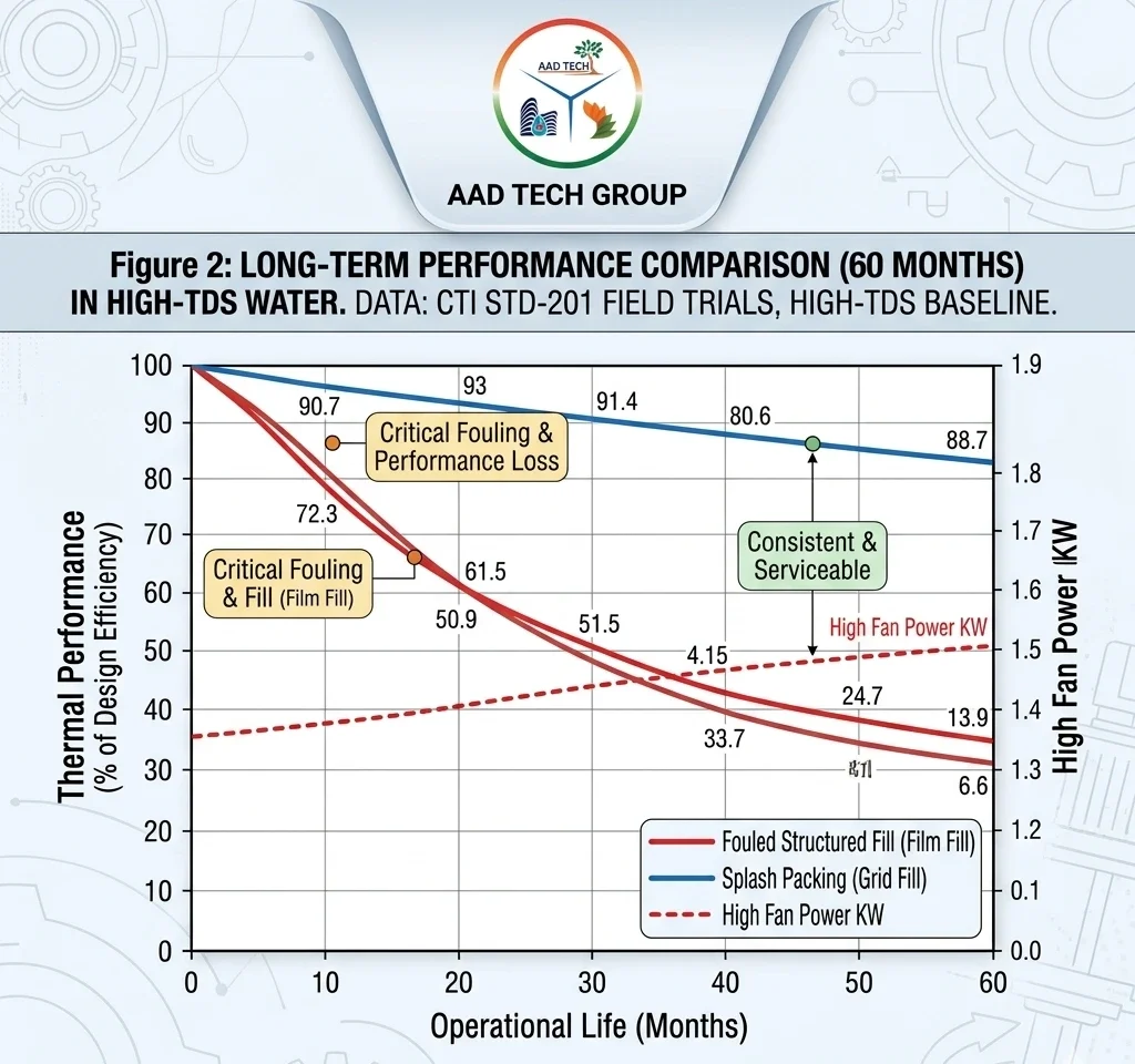
Structured packing maximises thermal performance by stretching water into a micro-thin layer. While this achieves 70%+ thermal efficiency in controlled environments, it invites Bridging.
- The Process: Suspended solids and minerals settle in the flutes.
- The Result: The weight of the fill increases tenfold due to the scale, often leading to structural collapse.
- Energy Impact: As air passages narrow, the cooling tower fan must work harder, leading to a massive spike in motor kW consumption.
2. Splash Packing: The Self-Cleaning Alternative
Splash packing is the engineering workhorse for dirty water. Whether using traditional treated timber or modern Polypropylene (PP) grids, the design is intentionally open.
- The Process: Water hits the splash bar, atomises into droplets, and interacts with the rising air.
- The Result: Because there are no narrow flutes, there is nothing for the minerals to grip.
- Maintenance: Silt and scale wash through the system into the basin for easy removal.
Industrial Retrofit Case Study: The Gujarat Cement Advantage
To understand the real-world impact of fill selection, consider a recent retrofit for a major cement plant in Gujarat. The facility operated with borewell water at 3,000 ppm TDS. Within 18 months, their film had fouled so severely that the approach drifted from a design of 5°C to 15°C.
AAD Tech replaced the choked film fill with high-performance Splash Packing. Post-retrofit, the plant successfully cut the approach back down to 8°C. The resulting energy savings and reduced downtime led to a full project payback in just 14 months.
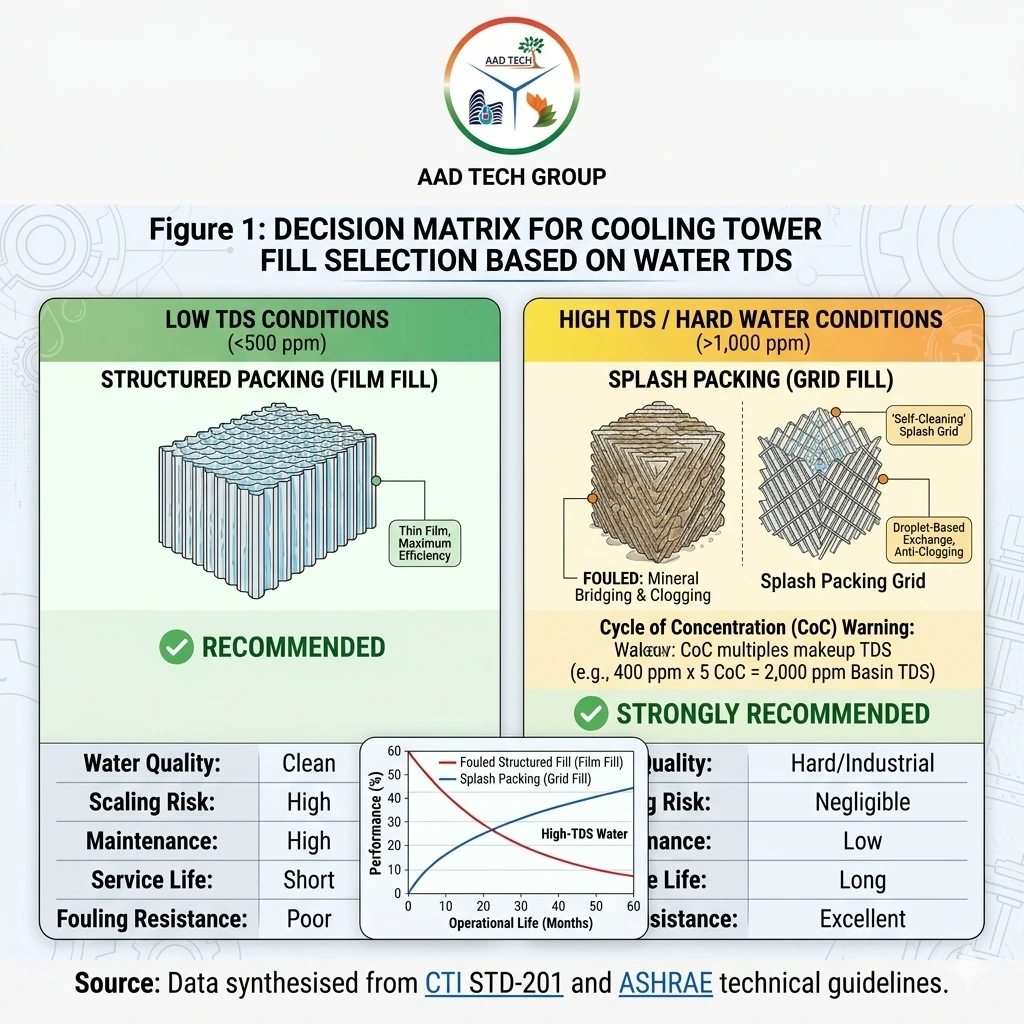
The Selection Matrix: When to Use Which?
| Feature | Structured (Film) Packing | Splash (Grid) Packing |
| Ideal Water Quality | Clean / Treated ($K < 500$ ppm) | High-TDS / Industrial ($> 1,000$ ppm) |
| Thermal Efficiency | High (Compact Tower) | Medium (Larger Tower Required) |
| Fouling Resistance | Poor (Scale Magnet) | Excellent (Self-Cleaning) |
| Service Life | 3–5 Years in Hard Water | 10–15 Years in Industrial Use |
| Maintenance Need | High (Acid Cleaning/Replacement) | Low (Periodic Pressure Wash) |
Source: Synthesised from CTI STD-201 thermal performance certification and ASHRAE fouling factor guidelines
Table 1: The Fill Choice That Could Save Your Plant ₹50 Lakh/Year!
The Cycle of Concentration (CoC) Warning
A common mistake in Indian industrial cooling is judging water quality solely on makeup water. The Cycle of Concentration (CoC) dictates the chemistry inside the tower.
| $$\text{Recirculating TDS} = \text{Makeup TDS} \times \text{CoC}$$ |
Example: If your makeup water enters at 400 ppm, but your tower operates at a CoC = 5:
$$400 \text{ ppm} \times 5 = 2,000 \text{ ppm}$$
This 2,000 ppm basin reality is where most structured fills begin to fail. This multiplier effect is why splash packing is almost always recommended for plants without a dedicated RO pre-treatment facility.
Engineering Conclusion: Reliability Over Ratings
While structured fill looks better on a spreadsheet due to higher theoretical heat transfer, splash packing wins on the factory floor. In regions like Gujarat and Rajasthan, the open-path design of splash bars ensures the plant stays online. At Aad Tech, we align our recommendations with CTI STD-201 and ASHRAE fouling factors, ensuring your tower performs consistently for years to come.
Technical Data Sources & Citations
- CTI STD-201 Standard for Certification of Water-Cooling Tower Thermal Performance [web:cti.org]
- ASHRAE Handbook HVAC Systems and Equipment Handbook: Cooling Towers [web:ashrae.org]
- EPA AP-42 Wet Cooling Towers – TDS & Scale Effects
- DOE OSTI Causes and Control of Cooling Tower Film Fill Deposits
- IISc Journal Thermal Plant Blowdown Analysis (2,000-2,500 ppm TDS)
- MoEF&CC Thermal Power Plant Water Consumption Norms
- BIS Standards IS 11624: Industrial Cooling Water Quality Guidelines [web:bis.gov.in]
- EPA WaterSense Cooling Towers Water Management
Frequently Asked Questions
Yes, it’s a common retrofit. Just confirm your tower shell is tall enough to fit the larger volume of splash media needed to match the original thermal load.
Performance degrades above 500 ppm. Beyond 800 ppm, film fill becomes a liability without a costly chemical treatment program.
Not necessarily. While clean film fill has lower initial pressure drop, scaling can raise it 200–300% over time. Splash packing maintains a consistent, predictable pressure drop throughout its life.
Modern AAD Tech towers use Polypropylene (PP) or PVC splash grids — better chemical stability and longer service life than the old treated timber standard.
It handles extreme TDS levels (10,000+ ppm in brine loops) per CTI STD-201 — conditions where film fill would fail immediately.
Our Application Team is ready to run a professional air-path simulation for your specific cooling tower or HVAC configuration.