
In the current industrial HVAC landscape, the shift toward Electronically Commutated (EC) fans is often framed as a universal upgrade. Their integrated electronics and high part-load efficiency make them an attractive proposition for modernising cooling tower performance.
But there is a static pressure wall where the elegance of EC technology meets the physics of high-resistance systems. Selecting a fan based on free-air delivery or low-resistance benchmarks is a recipe for system stalling and catastrophic energy waste. To achieve true optimisation, one must look beyond the brochure and into the pre-engineering realities of high static pressure.
1. Defining the High Static Pressure Threshold
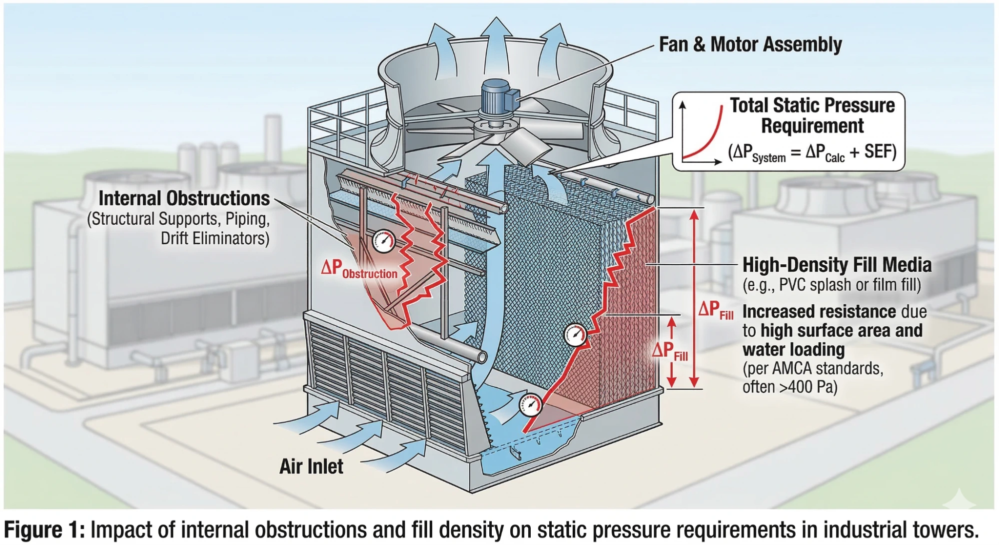
In industrial cooling applications, high static pressure is typically defined as resistance exceeding 250–500 Pa (approx. 1.0–2.0 in. wg). Per AMCA standards, industrial cooling towers often exceed 400 Pa solely due to the density of the fill media and drift eliminators.
The System Effect Factor (SEF)
A common pitfall in fan specification is ignoring the System Effect Factor. In a real-world cooling tower, elbows and dampers can easily add 100–200 Pa of unanticipated resistance. Applying SEF per AMCA Publication 201 is essential, as real-world $\Delta p_{system}$ can often exceed 600 Pa in dense fills.
2. EC Fan Limitations in High-Resistance Environments
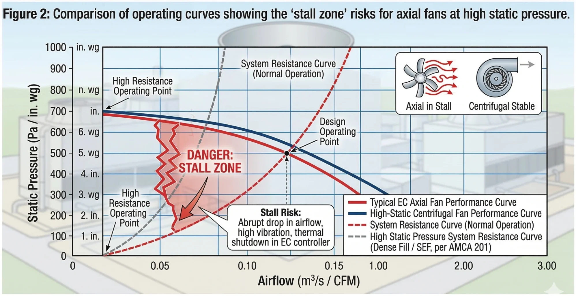
While EC motors are inherently efficient, the physics of the fan blades they drive cannot be bypassed. As static pressure increases, the power required to maintain airflow increases exponentially, while the pressure itself follows a squared relationship with speed.
The Fan Laws: Pressure vs Power
To maintain performance in high-resistance environments, engineers must respect the scaling of these variables as defined in ISO 12759:
- Pressure Relation: $p_2 = p_1 \times \left(\frac{n_2}{n_1}\right)^2$
- Power Relation: $P_2 = P_1 \times \left(\frac{n_2}{n_1}\right)^3$
3. Performance Matrix: EC Axial vs Centrifugal
When deciding between a modern EC axial setup and a traditional centrifugal arrangement, use the following quantifiable metrics based on industry performance benchmarks.
| Feature | EC Axial Fan | Centrifugal Fan |
| Pressure Handling | Optimal < 500 Pa; derates > 750 Pa | Superior > 750 Pa; stable curve |
| Stall Risk | High; thermal shutdown risk | Low; robust stall margin |
| Efficiency (Part-Load) | 80–90% peak | 70–80%; damper losses |
| Drive Type | Direct (low maint.) | Belt-driven (periodic checks) |
| Footprint | Compact inline | Larger plenum required |
| Cost (Initial/Opex) | Higher upfront; 30% savings | Lower upfront; higher running |
| Vibration Tolerance | Sensitive; electronics limit | High; industrial-grade |
Source: Compiled from ebm-papst technical data and AMCA Publication 201: Fans and Systems.
Table 1: Technical Comparison of EC Axial vs. Centrifugal Fans for High-Pressure HVAC Applications.
4. The Pre-Engineering Checklist
To avoid incorrect specification, follow these three critical steps:
- Calculate Total Resistance: Ensure $\Delta p_{system} = \Delta p_{calc} + 20\% \text{ SEF margin}$.
- Verify Noise at Operating RPM: Use manufacturer curves to check $dB$ levels, as high-pressure forces higher RPMs.
- Model Fan Arrays for Redundancy: Instead of one large centrifugal unit, consider 3x smaller EC fans. It provides “N+1” redundancy.
5. Impact on Cooling Tower Efficiency & ROI
The fan is the lungs of the cooling tower. Correct selection ensures the air-to-water ratio remains constant, directly impacting the Approach.
According to ASHRAE 90.1, correctly specified fans can cut energy consumption by 20–40% in variable-load towers.
6. Authority & Standards
- AMCA Publication 201: Fans and Systems.
- ISO 12759: Efficiency classification for fans.
- ASHRAE 90.1: Energy Standard for Buildings.
Frequently Asked Questions
Yes, but standard axial EC fans struggle above 500 Pa. Specialised centrifugal plug fans like the ebm-papst RadiPac series are required for pressures exceeding 1 kPa.
Airflow drops, vibration and noise increase, and the onboard controller may trigger speed derating or a hunting cycle, preventing the tower from meeting its thermal setpoint.
Upstream obstructions create turbulence that the EC controller interprets as an unstable operating point, causing it to limit RPM and starve the system of air.
A Fan Array is superior, it distributes pressure evenly, eliminates dead zones, and provides N+1 redundancy.
The Power Cube Law (P∝n3) means a 20% speed reduction cuts energy use by nearly 50%, accelerating payback in variable-load systems.