
For over a century, the AC induction motor has been the workhorse of the industry. However, in modern HVAC systems, the HVAC motor is often the single largest energy consumer in a building. Traditional induction motors are asynchronous and rely on electromagnetic induction, which creates inherent lag, friction, and waste heat.
The HVAC fan motor of the future is a hybrid. It takes the robust power of an AC supply and converts it into the precision of a Brushless DC (BLDC) motor through internal logic. This shift from slip to sync is not just a marginal gain; it is a fundamental leap in thermodynamic efficiency.
1. The Internal Anatomy: PMSM and Electronics
To understand the efficiency of electronically commutated (EC) motor HVAC systems now in demand, we must examine their Permanent Magnet Synchronous Motor (PMSM) architecture.
- The Stator: Fixed coils that receive pulsed current to create a rotating magnetic field.
- The Rotor: Unlike induction motors, which must induce a field, the EC rotor contains high-grade permanent magnets (typically Neodymium).
- The Logic: Because the rotor field is permanent and free, it moves in perfect synchronicity with the stator’s field. There is no slip, meaning no energy is lost trying to keep the rotor caught up with the magnetic frequency.
Image 1: Internal Anatomy Comparison
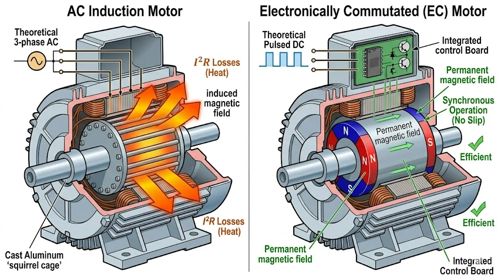
Source: Aadtech Engineering
This image directly supports Section 1 (Internal Anatomy) and Section 3 (Eliminating Rotor Losses). It provides a visual contrast between the asynchronous induction process (left) and the synchronous permanent magnet process (right), highlighting where energy is wasted as heat ($I^2R$ losses) in traditional motors.
2. The Commutation Process: Brushes vs. Transistors
In the early days of DC, commutation (switching the current direction) required physical carbon brushes, which caused friction, sparking, and mechanical wear.
In modern HVAC fan motor applications, these brushes are replaced by high-speed transistors (IGBTs). By removing mechanical contact, AadTech solutions eliminate the primary cause of motor burnout, ensuring a longer lifecycle and near-silent operation.
For a deeper dive into these components, see our guide on EC motor fundamentals and the benefits they offer.
3. The Physics of Efficiency: Eliminating Rotor Losses
Standard AC motors suffer from significant copper losses in the rotor. The power dissipated as the equation defines heat:
$$P_{loss} = I^2R$$
In an EC motor, because the magnetic field is provided by permanent magnets rather than induced current, the rotor current ($I$) is effectively zero. It allows for a total system efficiency of $\eta > 90\%$ across the entire speed curve.
The torque produced in these synchronous systems is governed by the relationship:
| $$\tau = \frac{3}{2}p\lambda I \sin(\delta)$$ |
Where $p$ is the number of pole pairs, $\lambda$ is the magnetic flux linkage, and $\delta$ is the torque angle. The integrated electronics optimise this angle in real-time, maintaining peak torque even at low RPMs where induction motors typically stall or overheat.
Image 2: Comparative Efficiency Curves
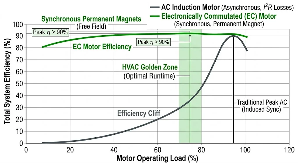
Source: What Is EC Technology And How It Is Better Than Non EC
4. Mapping the Performance: The Torque-Speed Curve
Understanding the HVAC motor performance requires looking at the three regions of the EC torque-speed curve:
- Constant Torque Region: From 0 to base speed, the motor delivers maximum torque. It is ideal for overcoming the static pressure of a high-resistance HVAC system during startup.
- Constant Power Region: Above base speed, the electronics employ field weakening to increase RPM while reducing torque, enabling high-velocity emergency ventilation.
- Peak Efficiency Zone: Unlike AC motors, which have a narrow sweet spot, EC motors maintain optimal performance over 70%-80% of their rated speed.
5. Integration: The VFD is Inside the House
A common misconception is that an EC motor requires an external Variable Frequency Drive. In reality, an EC motor is a VFD. It performs internal AC-to-DC rectification, pulsing the current back to the stator in precise sine waves.
This integration reduces the HVAC unit’s footprint and eliminates electromagnetic interference (EMI) often associated with long cable runs between a separate VFD and motor. It’s a cleaner, more compact physics solution for complex air handling.
6. Performance in HVAC: The Constant Airflow Advantage
The onboard electronics monitor Back EMF (Electromotive Force), allowing the motor to sense the environment. If a filter becomes clogged, the physics of the EC system allows it to detect the change in static pressure. The motor automatically calculates the exact torque needed to maintain a constant CFM. And that’s a feat a standard HVAC motor cannot achieve without expensive external sensors.
Explore why EC technology is fundamentally better than non-EC alternatives for these specific pressure-sensing applications.
| Feature | AC Induction Motor | EC Motor (Brushless DC) |
| Magnetic Field | Induced (Energy/Heat Loss) | Permanent (Zero Excitation) |
| Speed Control | External VFD Needed | Integrated (0-100% Precise) |
| Efficiency ($\eta$) | 60–75% (Drops at low speed) | 90–94% (High across full curve) |
| Maintenance | Brushes/Belts Wear | Brushless, Direct Drive |
| Noise/EMI | High Hum/Interference | Silent, Low EMI |
7. The Economics: Calculating ROI and Energy Savings
To justify the switch to an electronically commutated motor HVAC upgrade, we examine the Total Cost of Ownership (TCO).
The ROI Calculation Formula:
| $$ROI = \frac{(Cost_{AC\_Ops} – Cost_{EC\_Ops})}{Cost_{Upgrade\_Investment}}$$ |
On average, an AadTech EC motor upgrade yields a 30-40% reduction in energy consumption. For a 1HP fan motor running 24/7 in a commercial building, the 18-month ROI is validated by the U.S. Department of Energy (DOE) standards.
Frequently Asked Questions
Even at 100% load, EC motors are 15–20% more efficient because they eliminate the energy required to excite the rotor.
Yes. Most are designed as drop-in replacements, though they require a constant power supply as speed is regulated internally via 0-10V or PWM signals.
Removing physical brushes and using sine-wave commutation eliminates the high-frequency whine associated with traditional VFD-driven induction motors.
By monitoring Back EMF, the motor senses increased resistance and ramps up torque to maintain programmed airflow (Constant CFM).
AadTech modules are encapsulated to protect against moisture and vibration, typically outlasting the motor’s mechanical bearings.